I What is Step-down Transformer?
The step-down transformer is a transformer that converts the higher voltage at the input terminal into an ideal low voltage output, so as to achieve the purpose of step-down. The step-down transformer is a very important equipment in the power transmission and transformation system. Its normal operation not only relates to its own safety and reliable power supply for users but also directly affects the stability of the power system.
Under any circumstances, the transformer should not be burned, which will expand the accident and affect the stability of the power system.
The following mainly discusses its working principle, relay protection principle, operating conditions, operation and requirements, and abnormal operation and handling methods in detail.
II How does a Step-down Transformer Work?
1. Basic Principle
The basic principle of the step-down transformer is the principle of electromagnetic induction. Let's take a single-phase dual-winding transformer as an example to illustrate its basic working principle:
When a voltage is applied to the primary winding, the current flowing through the iron core will produce alternating flux. These magnetic fluxes are called the main magnetic flux, which will pass through the primary winding and the secondary winding, and the induced electromotive force will be generated in the winding. At this time, if the secondary side is connected to the load, the current will flow out to generate electric energy.
2. Explanation
The formula induced electromotive force is: E=4.44fNØm
In the formula:
|
E--the effective value of induced potential  F--frequency  N--the number of turns  Øm--the maximum value of the main magnetic flux |
Since the number of turns of the secondary winding is different from that of the primary winding, the magnitude of the induced electromotive force E1 and E2 are also different. After the internal impedance drops, the voltage will be different.
When the secondary side of the transformer is unloaded, only the current of the main magnetic flux flows through the primary side, which is called the excitation current. When a load is applied to the secondary side and the load current flows through, magnetic flux is also generated in the iron core, trying to change the main magnetic flux. However, when the primary voltage is unchanged, the main magnetic flux is unchanged, and two parts of the current will flow through the primary side. One part of it is the excitation current for balancing, so this part of the current will change. When the current is multiplied by the number of turns, we can obtain the induced electromotive force.
Common step-down voltage
Main input voltage of the step-down transformer: 460V, 380V, 220V, 400V
Output voltage: 380V, 220V, 110V, 36V, 24V
III Basic Operating Conditions
The 220kV step-down transformer cam transforms the 220kV high-voltage input to a low voltage. It can operate according to the nameplate under the specified cooling conditions. No matter where the transformer tap is located, as long as the applied voltage does not exceed 5% of the corresponding rated value, if the temperature meets the temperature rise requirement, the secondary side of the transformer can carry the rated current.
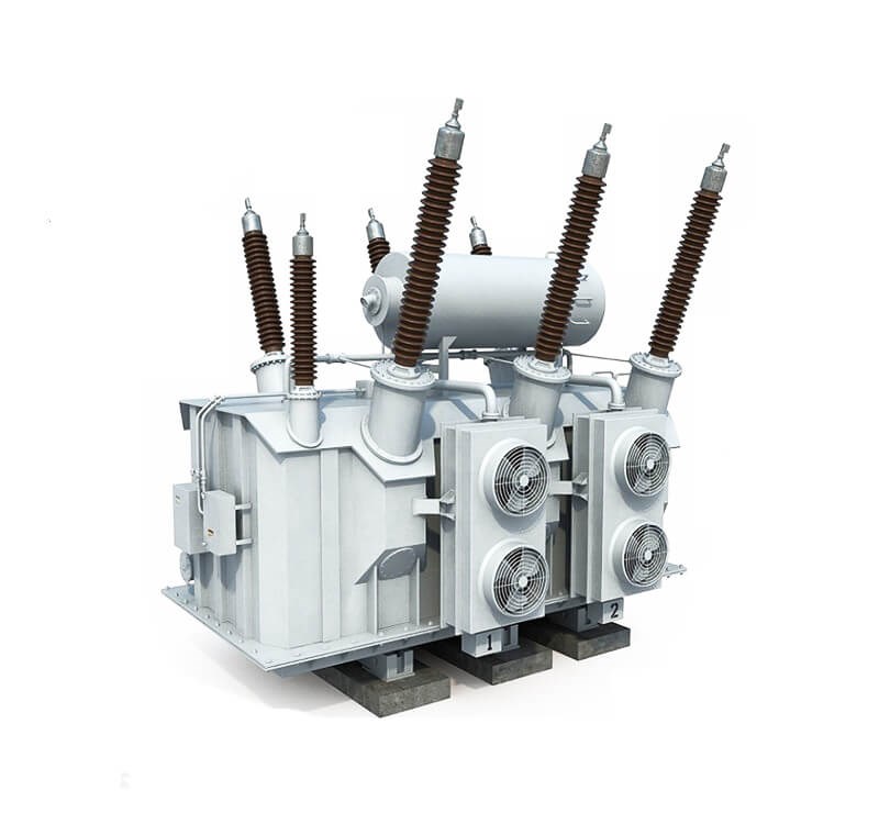
Figure 1. 220kv Step-down Transformer
For special use conditions, it is allowed to operate at a rated voltage not exceeding 110%. If there is no special requirement for the relationship between current and voltage, when the load current is K (K≤1) times the rated current, the following formula is used to limit the voltage U:
U(%)=110-5K2
1. Operation Requirements for 220kV Step-down Transformer Cooler
The transformer is not allowed to operate without a cooler. The cooler should be equipped with dual power supplies, and both power supplies are switched on during normal use, and each backs the other up.
When the main transformer cooler is in normal operation, in addition to the main use, it must be equipped with one set of auxiliary and one set of standby, which should be used in regular rotation as required.
2. Operating Requirements for Transformer Temperature Limit
The temperature of the upper oil and the temperature rise of various parts of the oil-immersed transformer shall not exceed a certain specified value during operation.
3. Requirements for Transformer Insulation Resistance
According to the requirements of the national standard, on the coil with the rated voltage above 1000V, the insulation resistance is measured with a 2500V megga, and on the coil with the rated voltage below 1000V, the insulation resistance is measured with 500 or 1000V megga.
The insulation absorption ratio R60/R15 of the transformer shall not be lower than 1.3. The insulation resistance of the transformer shall not be lower than the 700Ic value measured at the same temperature last time, and the minimum shall not be lower than 1 MΩ/kV.
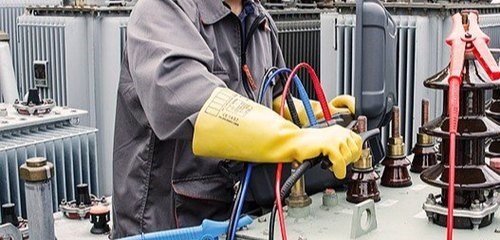
Figure 2. Measuring Insulation Resistance
IV General Operation and Requirements
The operation of the transformer must according to a complete operating system or regulation, and strictly follow the system or regulation.
1. All preparations must be made before the transformer is powered on. Check if the insulation resistance of the transformer is qualified, the cooling device is running normally, the residual gas is eliminated, and the oil level, oil color, bushing, etc. are normal, etc... After all preparations and inspections are completed, you can proceed to the next step.
2. Before you switch on the device, the protection device must be put in first, and check whether it is working normally and whether the cooler and transformer fire extinguishing system is normal.
3. Close the knife switch (close the knife switch on the power supply side first).
Except for special circumstances, it is strictly prohibited to charge from the low-voltage side of the transformer. When the transformer is charged from the high-voltage side, the neutral-point grounding switch should be put in. And after the charging is completed, it can be opened or not as required. For transformers in normal operation and standby, the heavy gas protection device should be placed in the trip position.
1. Impact Test Operation of Transformer
Set the transformer's quick-break protection device to be about 1.25 times the maximum three-phase short-circuit current on the low-voltage side. Input heavy gas input, and switch on 5 times at full voltage.
Record related data according to the switching operation and the relevant regulations of the at each impact. After the impact test is completed, run the device at no-load for 24 hours, and record the no-load current and oil surface temperature rise every hour.
2. Operation of On-load Tap Changer
Start the on-load tap changer before starting the transformer. The on-load device should be powered on first and then put into operation. Adjust the on-load tap should be adjusted step by step while monitoring the tap position and changes in voltage and current.
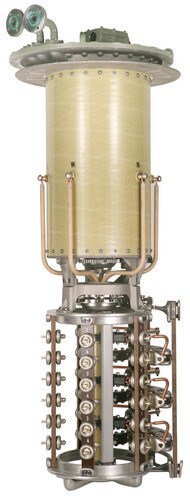
Figure 3. On load Tap Changer
3. Operation and Maintenance
Operation and maintenance is the most basic guarantee for the operation of equipment, and a corresponding scientific operation and maintenance system must be developed to match it.
For example, the main transformer in operation and standby should be checked regularly and flexibly. During peak hours, perform a light-off inspection to check whether there are discharge sparks, corona, and overheating, and burning everywhere in the joints. Special inspection systems are required for special circumstances.
V Abnormal Phenomenon and Handling Method
1. Abnormal Phenomenon
Some abnormal phenomenons inevitably occur during the operation of transformers. If we can discover them in time and take reasonable response measures, accidents can be greatly reduced. Common abnormalities of transformers mainly include:
1) Increased buzzing or abnormal pitch;
2) The temperature rises significantly or rapidly;
3) The oil level of the transformer or bushing is lower or higher than the allowable value, the oil color changes, and the test fails;
4) Cracks, discharge traces, or discharge sound appear in the casing;
5) The screw or wiring board is overheated and becoming red;
6) Light gas protection action;
2. Handling Method
Here are the causes and treatment methods of several common abnormalities:
(1) When the transformer temperature rises abnormally
1) Check the load condition of the transformer and whether the three-phase load is balanced. When an overload occurs, reduce the output and limit the load.
2) Check whether the radiator is related to the temperature of the device.
3) Check whether the cooler is operating normally; whether the ventilation device of the unit cooler is normal; if the fan motor breas down; whether the various fuses of the outage fan are blown out; whether the thermal overload relay is activated; whether the switch contact is good; whether the secondary circuit is disconnected, etc.
4) Check the thermometers of the transformer;
5) Check whether there is oil leakage or other reasons for a low oil level to cause the temperature to rise;
6) If the cooling device and the temperature measuring device are all in good condition, and the oil temperature still rises after the load is decreased, the transformer should be shut down immediately.
(2) Transformer oil level drops
If the oil level drops slowly, check whether the oil leaks or due to low temperature. If the oil level drops rapidly, stop the gas protection. Try to prevent the oil leakage immediately, and notify the maintainer to deal with it or fill the oil. If it can't handle, cut the power off.
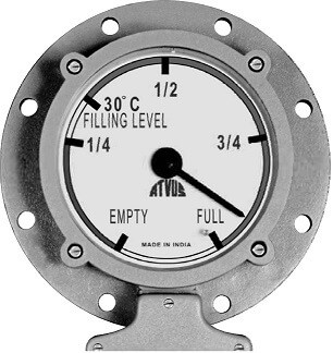
Figure 4. Oil Level Indicator of Transformer
(3) Light gas protection action
If there is a backup transformer, put it in; if there is none, you should pay close attention to the operation of the transformer, and it is strictly forbidden to exit the heavy gas protection at this time.
Take gas and oil samples in the gas for analysis;
check whether there is gas in the gas relay of the transformer to determine whether the protection is activated.
Before the inspection, the signal should be input into the protection pressure plate, and the trip should be performed after sampling.
If there is an internal failure of the transformer, it must be shut down. If there is air inside, the gas relay valve should be opened to release the air. If the gas protection is faulty, abnormal or the secondary circuit is poorly insulated, the tripping out relay should be disconnected.
(4) Transformer overload operation
Before overload operation, check whether the transformer has serious defects (such as abnormal cooling system, serious oil leakage, partial overheating, abnormal dissolved gas in oil, etc.) or insulation weakness. If so, it should not be in overload operation.
When the transformer is running under overload, the backup cooler should be immediately put in to observe the temperature of the upper layer of the transformer, the ambient temperature, and the time. And record the overload time and overload multiple, the overload multiple during normal overload operation.
Question: Can a Step-down Transformer be used as a step-up transformer?
First, you need to understand the characteristics of the transformer. The transformer is a common electrical equipment that can be used to transform a certain value of alternating voltage into another value of alternating voltage with the same frequency.
A step-up transformer is a transformer used to transform a low-value alternating voltage into another higher-value alternating voltage of the same frequency, while a step-down transformer converts the higher voltage at the input of the power supply into an ideal lower voltage for the load. The principle of the transformer is to transfer the energy through electromagnetic conversion and play the role of electrical isolation, as shown in the Figure below.
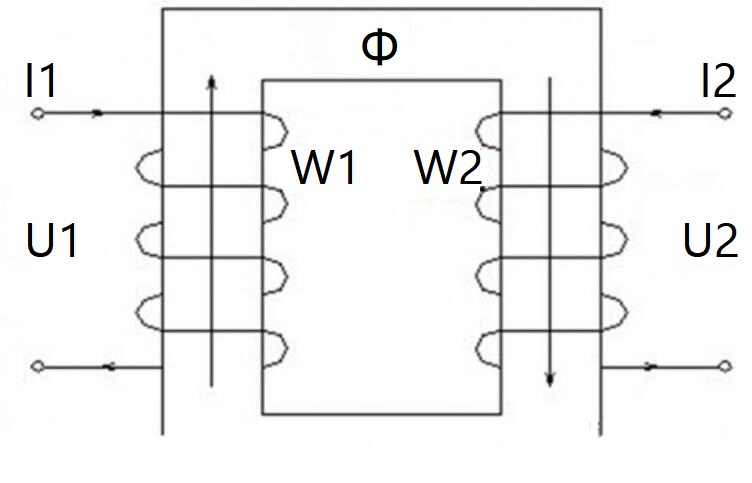
Figure 5. Working Principle of the Transformer
I1 (I2), U1 (U2), W1 (W2) are the current, voltage, and the number of turns of the primary (secondary) winding, respectively, and the relationship between them is U1/U2=W1/W2=I2/I1.
Φ is the magnetic line of force generated by electromagnetic induction. The physical entity it is in is the iron core, which is the magnetic circuit of the transformer.
In the step-down transformer, the primary winding is of high voltage and the current is small, but because Φ is generated by electromagnetic induction, the loss of it must be considered. Therefore, the primary winding voltage should reserve 5% of the loss, such as for 10KV, it is actually 10.5 KV.
The secondary winding is of low voltage and the current is large. It is necessary to consider the voltage drop of the winding itself and the load end (electrical equipment). Therefore, the voltage should also be reserved for about 5% margin. For example, generally speaking, for the 380V voltage, it is actually 400V on the low-voltage side of the transformer.
Then, if the step-down transformer is used as a step-up transformer, the electromagnetic induction should be generated on the low-voltage side, and the high-voltage side is used as the load power supply, both of which need to consider corresponding loss. If both are reserved 5% margin, this operation can be achieved. Moreover, the output voltage of the inverter has a large adjustable range, which can meet the requirements.
In other words, in principle, the step-down transformer can be used as a step-up transformer.
However, in the actual application, the structure and protection of the step-down transformer are different from that of the step-up transformer. Long-term reverse use will slowly reduce the stability of the transformer and may affect its service life.

Contact Us
 QQ:843349690
 E-mail:PM@Tektstar.com
 Phone:18126161077


 Copyright:Shenzhen TektStar Technology CO., LTD.
-
Phone
18126161077 -
Wechat